Don't loose your PV-power to the Grid. Here's a cheap DIY-solution to keep the PV-energy in your home!
General idea
In Germany it was common to earn more than 40ct per kWh if you had a PV-power plant on top of your roof in 2009. Since than everything changed: the feed-in tariff dropped to less than 8ct per kWh in 2025, while you still have to pay 26ct to 35ct per kWh if you consume energy. That's the reason why you should install a battery to your home, to store the PV-energy over the day to make use of it in the afternoon and night. But for this your system has to track the current power-demand to adjust the PV-/battery-inverter to only this power-level you are currently consuming.
There are several turnkey solutions on the market from Varta and other companies. But I like the idea of having control over my own system, especially as some manufacturers have attracted negative attention for shutting down their systems remotely.
Brief overview of the Victron eco-system
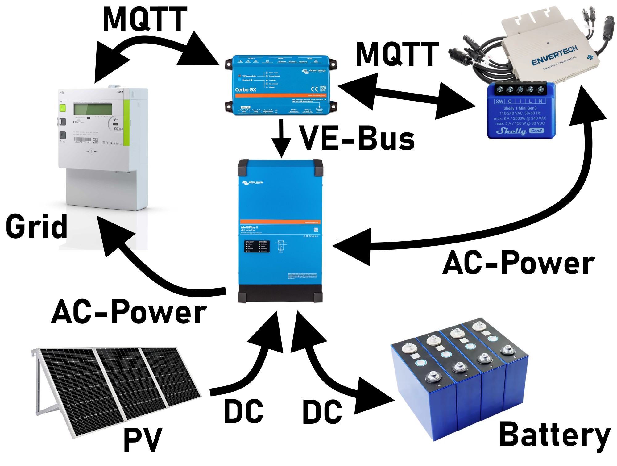
Victron offers some nice components that can be combined to create a so called ESS - an Energy Storage System. Here a PV Maximum Power Point Tracker (MPPT) is converting the PV-voltage to the voltage-level of the battery. A second device - an inverter - converts the DC-voltage of the battery to an AC-voltage for the grid-feed-in. Victron supports several energy-meters like the Carlo Gavazzi EM24, but I wanted to reduce the cost and increase the functions of my ESS at the same time.
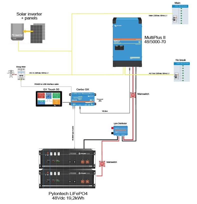
The following picture shows an ESS-configuration with AC-connected PV and a battery-system:
As I already had several AC-connected micro-PV-inverters made by Envertech, I wanted to take care of these inverters while using the nice Victron GUI at the same time. Sorrowly the Envertech-inverters have only a proprietary power-line-communication-interface that is not supported by Victron. So I had to find a cheap solution here.
To control my ESS, Victron supports only two or three energy-meters that costs around 150€ to 200€. So I search for a better solution, because...
Reading the common grid-meter
...since a couple of years houses in Germany received modern grid-meters with at least an Infrared-communication. This communication-interface provides information about the actual power (positive for consumption, negative for feeding power to the grid). My idea was, to use a RaspberryPi next to this grid-meter, to read the IR-diode using one of the UART-interfaces. My Landis&Gyr grid-meter uses the Smart Message Language (SML) and outputs a bunch of status-information over the IR-diode every second. So I downloaded jSML from openMUC jSML Project and programmed a small Java-application for my Raspberry Pi.
Within the SML-protocol the most important information are the values for the actual power, as well as values for 1.8.0 (consumption) and 2.8.0 (feed-in). The actual power is transmitted with the SML-object with the HEX-code "01 00 10 07 00 FF". If you like more information, you can have a look in my GitHub-project for the GridMeter.
If a valid value is received, it will be forwarded to my MQTT-broker as Victron supports MQTT and this is a very common method to exchange data between different systems that are not compatible at a first glance. Now I was aware of my power-demand without an extra device as I already had my Raspberry Pi next to the grid-meter - but a dedicated ESP8266 is possible, too.
Connecting Envertech EVT560 inverters without Enverbridge
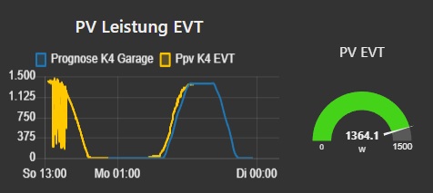
As I said, I already had some micro-inverters for some PV-panels on top of my roof. I tested the so called "Enverbridge" but this was a very bad idea. This device looked like a device from the 90s and was cloud-based to the Envertech-cloud. Nothing I'd like to use. So I bought a small Shelly Energy-Meter, put it in between the micro-inverters and the grid and configured the Shelly to send the actual power to the MQTT-broker. Thats all I had to do to get a very nice looking graph in NodeRED as well:
Adding grid-meter to RaspberryPi-based CerboGX using Victrons VenusOS
Now that my MQTT-broker has knowledge about the actual power-demand of our house, I had to implement a new service in the CerboGX to receive my MQTT-messages and feed them into the dBus-message-system of Victrons CerboGX-system. Here Victron already prepared to implement own devices as Grid-Meters or as PV-inverters (what we are going todo in a second step).
So first, I had to write a python-script, that subscribes to my MQTT-topics and receive the actual power from the grid-meter. I used the code of a fronius smartmeter from RalfZim on GitHub. The script creates a new dBus-service and registers as productID 45069, which is the Victron-internal ID for an ac-meter. The DeviceType is set to 345, which corresponds to the energy-meter ET340. The role is set to "grid":
class DbusDummyService:
  def __init__(self, servicename, deviceinstance, paths, productname=METER_PRODUCT_NAME, connection=METER_CONNECTION_NAME):
    self._dbusservice = VeDbusService(servicename)
    self._paths = paths

    logging.debug("%s /DeviceInstance = %d" % (servicename, deviceinstance))

    # Create the management objects, as specified in the ccgx dbus-api document
    self._dbusservice.add_path('/Mgmt/ProcessName', __file__)
    self._dbusservice.add_path('/Mgmt/ProcessVersion', 'Unkown version, and running on Python ' + platform.python_version())
    self._dbusservice.add_path('/Mgmt/Connection', connection)

    # Create the mandatory objects
    self._dbusservice.add_path('/DeviceInstance', deviceinstance)
    self._dbusservice.add_path('/ProductId', 45069) # 45069 = value used in ac_sensor_bridge.cpp of dbus-cgwacs, found on https://www.sascha-curth.de/projekte/005_Color_Control_GX.html#experiment - should be an ET340 Engerie Meter
    self._dbusservice.add_path('/DeviceType', 345) # found on https://www.sascha-curth.de/projekte/005_Color_Control_GX.html#experiment - should be an ET340 Engerie Meter
    self._dbusservice.add_path('/Role', 'grid')


    self._dbusservice.add_path('/ProductName', productname)
    self._dbusservice.add_path('/FirmwareVersion', 0.1)
    self._dbusservice.add_path('/HardwareVersion', 0)
    self._dbusservice.add_path('/Connected', 1)
    self._dbusservice.add_path('/Position', 0) # DSTK_2022-10-25 bewirkt nichts ???
    self._dbusservice.add_path('/UpdateIndex', 0)

    for path, settings in self._paths.items():
      self._dbusservice.add_path(
        path, settings['initial'], gettextcallback=settings['textformat'], writeable=True, onchangecallback=self._handlechangedvalue)
Now that the service is installed I had to program the main-loop to register the device-tree to show power, voltage, current and energy within the Victron GUI:
def main():
  thread.daemon = True # allow the program to quit

  from dbus.mainloop.glib import DBusGMainLoop
  # Have a mainloop, so we can send/receive asynchronous calls to and from dbus
  DBusGMainLoop(set_as_default=True)

  # formatting
  def _kwh(p, v): return (str(round(v, 2)) + 'kWh')
  def _wh(p, v): return (str(round(v, 2)) + 'Wh')
  def _a(p, v): return (str(round(v, 2)) + 'A')
  def _w(p, v): return (str(int(round(v, 0))) + 'W')
  def _v(p, v): return (str(round(v, 1)) + 'V')
  def _hz(p, v): return (str(round(v, 2)) + 'Hz')

  global dbusservice
  dbusservice = DbusDummyService(
    #servicename='com.victronenergy.grid',
    servicename='com.victronenergy.grid.cgwacs_edl21_ha',
    deviceinstance=0,
    paths={
      '/Ac/Power': {'initial': None, 'textformat': _w},
      '/Ac/L1/Voltage': {'initial': None, 'textformat': _v},
      '/Ac/L2/Voltage': {'initial': None, 'textformat': _v},
      '/Ac/L3/Voltage': {'initial': None, 'textformat': _v},
      '/Ac/L1/Current': {'initial': None, 'textformat': _a},
      '/Ac/L2/Current': {'initial': None, 'textformat': _a},
      '/Ac/L3/Current': {'initial': None, 'textformat': _a},
      '/Ac/L1/Power': {'initial': None, 'textformat': _w},
      '/Ac/L2/Power': {'initial': None, 'textformat': _w},
      '/Ac/L3/Power': {'initial': None, 'textformat': _w},
      '/Ac/Energy/Forward': {'initial': None, 'textformat': _kwh}, # energy bought from the grid
      '/Ac/Energy/Reverse': {'initial': None, 'textformat': _kwh}, # energy sold to the grid
    })
  mainloop = gobject.MainLoop()
  mainloop.run()
The MQTT-Client is then defined using PahoMQTT, a nice library to interact with an MQTT-broker:
# Konfiguration MQTT
client = mqtt.Client(MQTTNAME) # create new instance
if (MQTT_USERNAME != "") and (MQTT_PASSWORD != ""):
    client.username_pw_set(MQTT_USERNAME, MQTT_PASSWORD)
client.on_disconnect = on_disconnect
client.on_connect = on_connect
client.on_message = on_message
client.connect(MQTT_BROKER_ADDRESS)  # connect to broker
client.loop_start()
Within the on_message() function on receiving new MQTT-topics, the individual information are put to the designated variables:
def on_message(client, userdata, msg):

    try:

        global power_sum, power_l1, power_l2, power_l3, energy_180, energy_280, dbusservice

        if msg.topic == MQTT_PATH + "/power":
            # power in W
            power_sum = float(msg.payload)
            power_l1 = power_sum/3;
            power_l2 = power_sum/3;
            power_l3 = power_sum/3;
        elif msg.topic == MQTT_PATH + "/p_l1":
            power_l1 = float(msg.payload)
        elif msg.topic == MQTT_PATH + "/p_l2":
            power_l2 = float(msg.payload)
        elif msg.topic == MQTT_PATH + "/p_l3":
            power_l3 = float(msg.payload)
        elif msg.topic == MQTT_PATH + "/180":
            # energy in kWh
            energy_180 = round(float(msg.payload) / 1000, 3)
        elif msg.topic == MQTT_PATH + "/280":
            # energy in kWh
            energy_280 = round(float(msg.payload) / 1000, 3)

        dbusservice._update()

    except Exception as e:
        logging.exception("Programm MQTTtoMeter ist abgestuerzt. (during on_message function)")
        print(e)
        print("Im MQTTtoMeter Programm ist etwas beim auslesen der Nachrichten schief gegangen")
From now on, on each MQTT-topic the values are updated within the Victron VenusOS. As the device is declared as a grid-meter, the control-loop to control the output-power (or input-power) of the Multiplus II DC/AC-inverter works in the same way as with a supported energy-meter like the ET340 or EM24 - but much cheaper as I'm using only a single IR-reader combined with my already available RaspberryPi.
Adding Envertech EVT560 to the Victron GUI
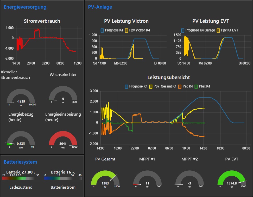
Comparable to the grid-meter, Victron offers interfaces to add external PV-inverters to the GUI. Again we have to implement a new Python-script, that installs another dBus-service. Now we are using the ProductId 0xFFFF for a dummy-device that magically creates an external PV-inverter. Most of the python-script is just a copy&paste of the grid-meter-script. In the end, the GUI looks like this if everything works:
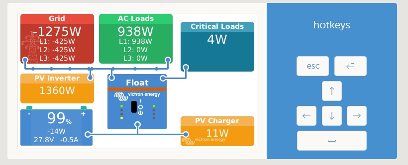
As my battery is filled at 99%, the PV charger is controlled down to 11W while the external micro-inverters are feeding-in 1360W to the grid (they cannot be controlled like the Victron inverter). In the evening-hours, the system controlls the battery-inverter in such a way, that only the power-demand of the house is compensated and only this amout of power is fed to the house-grid, that the components are consuming.
The surplus power could be used to power some fans, water pumps or additional lighting within the house. The Victron-control-system is taking care of the battery-level and the AC-power and NodeRED controls the high-level-functions:
Sourcecode and Outlook
You can download both scripts from my GitHub repository mqtt2victron.
The general configuration can be done in the config.ini (like MQTT-broker or the MQTT-Path). But if you like to change the specific topics, you have to look into the two python-scripts and change the individual lines.
Comments