Motorcontrollers are everywhere, cheap and reliable, but building a field-oriented control (FOC) from scratch to understand the details is a nice challenge. So I accepted the challenge and implemented a full-featured FOC within an FPGA.
If you want a ready-to-go controller for a motor-application, you can take a dedicated microcontroller like the TI C2000 with the InstaSPIN-FOC and you are good to go within minutes. The documentations of these kind of tools are very detailed and full of background-information. But for learning-purposes I like to implement things on my own first, to understand the basic details. In this post I will not start from scratch presenting the basics of motor-controllers, but will focus on the implementation on an FPGA as this is something I couldn't find on the internet up to now.
General overview of a FOC
The general idea of a field-oriented control is, that the current-controller rotates synchronized with the rotor-field - hence field-orientated. This has some benefits regarding the controller compared to stator-oriented controls. The general idea is to have two (slower) PI-controllers that control the d and q part of the motor-current. The d-part of the stator-current controls the magnetic flux density of the rotor, while the q-part of the stator-current controls the torque. So this q-part defines how strong the rotor is driven, while the d-part can be used to apply field-weakening to allow higher rotational speeds - at the expense of a reduced torque, keeping the power (speed x torque) constant.

When you are searching for FOCs, most of the results are for the common 3-phase motors. But from an old project I have a spare 6-phase BLDC motor here, that I like to run again - that's an additional challenge.
Now that we have a general idea of what we are going to implement, lets dive into the individual signals. For each signal I will show some simulations using the software Plexim PLECS followed by the approach I took to implement it within VHDL.
1. Decoding hall-sensors
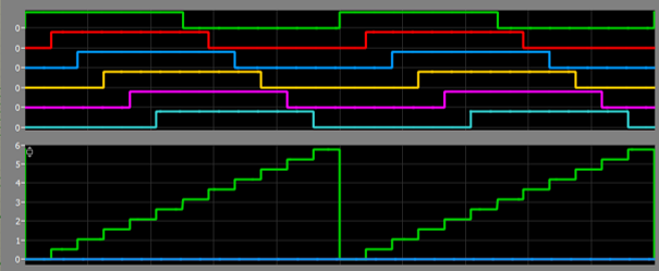
The BLDC I'm going to drive has a hall-sensor attached to each phase. So I have to read six individual signals and try to convert them to the rotor-position as the motor has no sensor for the absolute angle. As each hall-sensor outputs a digital signal I converted these digital signals to a rough sawtooth-signal:
As we like to get the rotor-position, this rough sawtooth-signal can be converted to an alpha-/beta-signal using a simple lookup-table. Alpha/Beta-coordinates are used in a biaxial coordinate system to represent the motor-currents. In VHDL I'm using a simple state-machine to create these two signals:
case unsigned'(f & e & d & c & b & a) is
    when "000001" => -- sector 0
        alpha_int <= to_signed(0, 32);
        beta_int <= to_signed(-65536, 32);
        theta_int <= to_signed(0, 32);      -- 2*pi * (0/12)
    when "000011" => -- sector 1
        alpha_int <= to_signed(32768, 32);
        beta_int <= to_signed(-56756, 32);
        theta_int <= to_signed(34315, 32); -- 2*pi * (1/12)
    when "000111" => -- sector 2
        alpha_int <= to_signed(56756, 32);
        beta_int <= to_signed(-32768, 32);
        theta_int <= to_signed(68629, 32); -- 2*pi * (2/12)
    when "001111" => -- sector 3
        alpha_int <= to_signed(65536, 32);
        beta_int <= to_signed(0, 32);
        theta_int <= to_signed(102944, 32); -- 2*pi * (3/12)
    when "011111" => -- sector 4
        alpha_int <= to_signed(56756, 32);
        beta_int <= to_signed(32768, 32);
        theta_int <= to_signed(137258, 32); -- 2*pi * (4/12)
    when "111111" => -- sector 5
        alpha_int <= to_signed(32768, 32);
        beta_int <= to_signed(56756, 32);
        theta_int <= to_signed(171573, 32); -- 2*pi * (5/12)
    when "111110" => -- sector 6
        alpha_int <= to_signed(0, 32);
        beta_int <= to_signed(65536, 32);
        theta_int <= to_signed(205887, 32); -- 2*pi * (6/12)
    when "111100" => -- sector 7
        alpha_int <= to_signed(-32768, 32);
        beta_int <= to_signed(56756, 32);
        theta_int <= to_signed(240202, 32); -- 2*pi * (7/12)
    when "111000" => -- sector 8
        alpha_int <= to_signed(-56756, 32);
        beta_int <= to_signed(32768, 32);
        theta_int <= to_signed(274517, 32); -- 2*pi * (8/12)
    when "110000" => -- sector 9
        alpha_int <= to_signed(-65536, 32);
        beta_int <= to_signed(0, 32);
        theta_int <= to_signed(308831, 32); -- 2*pi * (9/12)
    when "100000" => -- sector 10
        alpha_int <= to_signed(-56756, 32);
        beta_int <= to_signed(-32768, 32);
        theta_int <= to_signed(343146, 32); -- 2*pi * (10/12)
    when "000000" => -- sector 11
        alpha_int <= to_signed(-32768, 32);
        beta_int <= to_signed(-56756, 32);
        theta_int <= to_signed(377460, 32); -- 2*pi * (11/12)
    when others =>
        -- unexpected state
        -- keep last values for alpha_int and beta_int
end case;
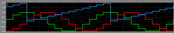
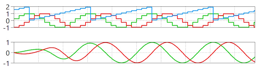
The resulting curves look like this: green = alpha, red = beta, blue = current sector based on hall-signals:
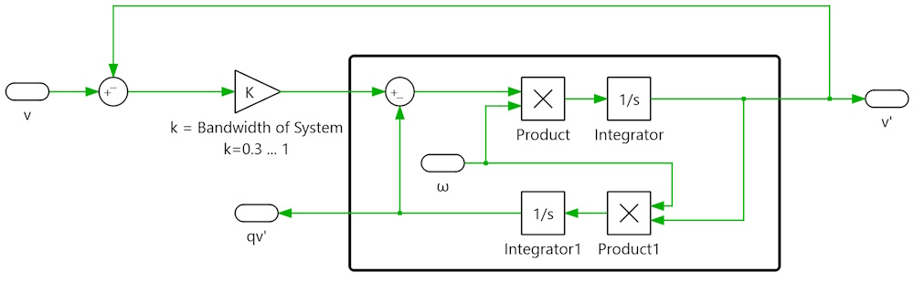
I have to admit, that this rotor-position-signal is still very rough. So my approach was to use a second-order-generalized-integrator (SOGI) to create a phase-aligned signal with much higher resolution. For this two multiplications and two integrators are used:
As we have alpha and beta at the same time, I implemented a Dual-SOGI using both signals to get a better performance. As you can see in the following plot, the signal-processing takes around one periode to get in sync with the input and create a perfect alpha/beta signal:
The VHDL-code of this function is quite long and would go beyond of the scope of this blog-post. So you can find the code in the file sogi.vhd. As I'm using a pipelined multiplicator it takes 18 steps to calculate the output of an incoming sample. As I'm clocking the individual blocks at 100MHz it takes 180ns to get a new value here.
2. Calculating rotor angle
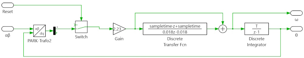
Now that I had a very nice and smooth signal for the rotor-position, I searched for a solution to calculate the absolute rotor-angle based on alpha and beta. In grid-connected PV-inverters I had good experiences with a so called Phase-Locked-Loop (PLL) so I gave it a try and first implemented a PLL within the simulation:
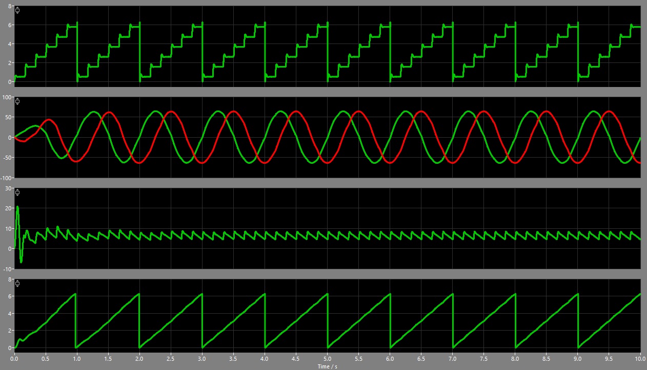
The resulting angle was looking very well:
So I decided to implement this in the logic as well. First I had to apply the park-transformation to convert the alpha/beta-signals to d/q-signals, followed by a PI-controller and a phase-accumulation at the end:
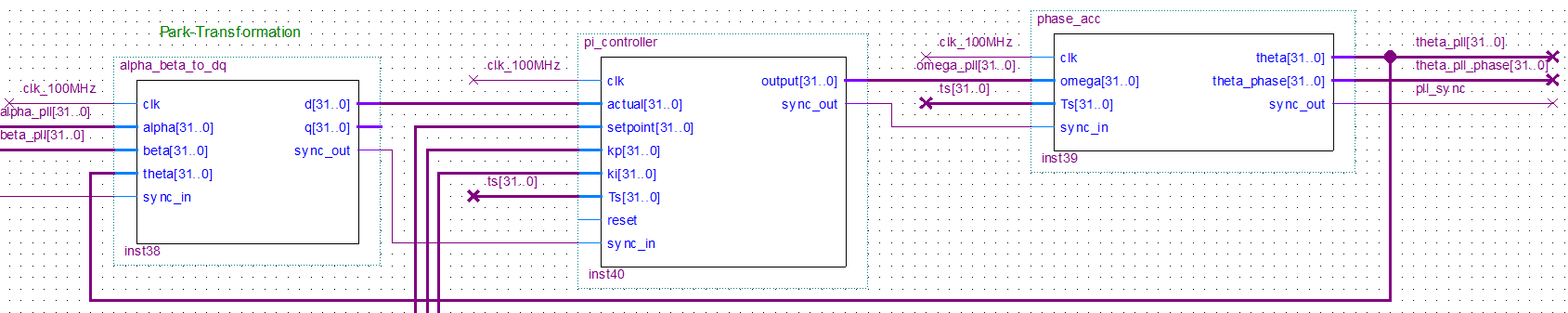
Park-Transformation The park-transformation follows the equation:
But wait - there are some sine- and cosine-calculations... Those trigonometric functions are not available within the FPGA per se. My solution was the application of the Coordinate Rotation Digital Computer algorithm - in short CORDIC. This iterative algorithm is able to calculate several things like exponential function, logarithms - and the desired trigonometric functions and is used in the x87-mathematic Co-Processor of Intel for instance. So I imported an implementation of the CORDIC-algorithm by Mitu Raj and Roshan Raju into my VHDL-file of the park-transformation:
component cordic_mini is
generic(
    XY_WIDTH    : integer := 16;                            -- OUTPUT WIDTH
    ANGLE_WIDTH : integer := 16;                          -- ANGLE WIDTH
    STAGE       : integer := 14                           -- NUMBER OF ITERATIONS
);
port(
    clock      : in  std_logic;                           -- CLOCK INPUT
    angle      : in  signed (ANGLE_WIDTH-1 downto 0);     -- ANGLE INPUT from -360 to 360
    load       : in  std_logic;                           -- LOAD SIGNAL TO ENABLE THE CORE
    reset      : in  std_logic;                           -- ASYNC ACTIVE-HIGH RESET
    done       : out std_logic;                           -- STATUS SIGNAL TO SHOW WHETHER COMPUTATION IS FINISHED
    Xout       : out signed (XY_WIDTH-1 downto 0);        -- COSINE OUTPUT
    Yout       : out signed (XY_WIDTH-1 downto 0)         -- SINE OUTPUT
);
end component;
So now I was able to calculate the desired park-transformation:
if (sync_in = '1' and state = 0) then
    -- rescale theta from 0..2*pi to 0...+1 as cordic implementation accepts values between -1 to +1 and interpretes as -360 to +360
    mult_in_a <= shift_right(theta, 1); -- theta/2
    mult_in_b <= to_signed(5215, 32); -- 1/(2*pi) = 0.159149169921875
    state <= 1; -- start of state-machine

elsif (state = 1) then
    -- convert Q15.16 to Qx.15 of calculate (theta / (2 * pi))
    theta_int <= resize(shift_right(mult_out, 15), 16);
    reset_cordic <= '1'; -- reset the cordic to start new process in next step
    start_cordic <= '0';
    state <= state + 1;

elsif (state = 2) then
    -- stop resetting
    reset_cordic <= '0';
    state <= state + 1;

elsif (state = 3) then
    -- start mini-cordic. As it takes 16 clocks to calculate we have to wait until it is ready
    start_cordic <= '1';
    state <= state + 1;

elsif (state = 4 and cordic_mini_done = '1') then
    -- copy the calculated values for sine and cosine into internal signals
    sine_int <= shift_left(resize(sine, 32), 1); -- convert Q0.15 into Q15.16
    cosine_int <= shift_left(resize(cosine, 32), 1); -- convert Q0.15 into Q15.16
    state <= state + 1;

elsif (state = 5) then
    -- load the multiplier with alpha * cos(theta)
    mult_in_a <= alpha;
    mult_in_b <= cosine_int;
    state <= state + 1;

elsif (state = 6) then
    -- copy result to temp-signal and load the multiplier with beta * sin(theta)
    mult_out_tmp <= resize(shift_right(mult_out, 16), mult_out_tmp'length);
    mult_in_a <= beta;
    mult_in_b <= sine_int;
    state <= state + 1;

elsif (state = 7) then
    -- copy result to d and load the multiplier with beta * cos(theta)
    d <= resize(mult_out_tmp + shift_right(mult_out, 16), 32);
    mult_in_a <= beta;
    mult_in_b <= cosine_int;
    state <= state + 1;

elsif (state = 8) then
    -- copy result to temp-signal and load the multiplier with alpha * sin(theta)
    mult_out_tmp <= resize(shift_right(mult_out, 16), mult_out_tmp'length);
    mult_in_a <= alpha;
    mult_in_b <= sine_int;
    state <= state + 1;

elsif (state = 9) then
    -- copy result to q and complete calculation
    q <= resize(mult_out_tmp - shift_right(mult_out, 16), 32);
    sync_out <= '1';
    state <= state + 1;

elsif (state = 10) then
    -- go back to idle-state
    sync_out <= '0';
    state <= 0;

end if;
PI-Controller The d-part of the park-transformed signals I then fed into a simple PI-controller to calculate the omega, containing the actual speed of the machine:
if (sync_in = '1' and state = 0) then
    -- copy external signals to internal signals
    actual_int <= actual;
    setpoint_int <= setpoint;
    kp_int <= kp;
    ki_int <= ki;
    Ts_int <= Ts;
    state <= 1; -- start of state-machine

elsif (state = 1) then
    -- calculate the error and ki*Ts
    error <= resize(setpoint_int - actual_int, error'length);
    i_gain_ts <= resize(shift_right(ki_int * Ts_int, 21), 32); -- Q10.21 * Q0.31 = Qx.52 -> convert to Q0.31
    state <= state + 1;

elsif (state = 2) then
    -- calculate proportional and integral parts
    p_part <= resize(shift_right(kp_int * error, 9), p_part'length); -- Q10.21 * Q11.12 = Qx.33 -> convert to Q23.24
    i_inc <= resize(shift_right(i_gain_ts * error, 19), i_inc'length); -- Q0.31 * Q11.12 = Qx.43 -> convert to Q23.24
    state <= state + 1;

elsif (state = 3) then
    -- integrate
    i_part <= i_part + i_inc;
    state <= state + 1;

elsif (state = 4) then
    -- calculate output
    output <= resize(shift_right(p_part + i_part + omega_init, 8), output'length); -- convert Q23.24 to Q15.16
    sync_out <= '1';
    state <= state + 1;

elsif (state = 5) then
    sync_out <= '0';
    state <= 0;

end if;
Phase accumulation Finally, the output of the PI-controller (hence, omega) is fed into another integrator that resets above 2*PI or below zero:
if (sync_in = '1' and state = 0) then
    -- calculate omega * Ts
    MUL_1 <= resize(shift_right(omega * Ts, 26), 24); -- Q15.16 * Q0.31 = Qx.47 -> convert to Qx.21
    state <= 1; -- start of state-machine

elsif (state = 1) then
    -- integrate the result
    SUM <= MUL_1 + theta_int;
    state <= state + 1;

elsif (state = 2) then
    -- check the limits and reset integrator above 2*PI or below 0
    if SUM >= TWO_PI then
        theta_int <= SUM - TWO_PI;
    elsif SUM < to_signed(0, 32) then
        theta_int <= SUM + TWO_PI;
    else
        theta_int <= SUM;
    end if;
    state <= state + 1;

elsif (state = 3) then
    -- we shift theta by -pi/2 to get a theta to calculate alpha/beta
    -- as we are calculating Theta based on a 12-step alpha/beta based on the hall-signals
    -- we have to shift theta by +pi/12 to get the resulting alpha/beta in phase
    SUM2 <= theta_int + to_signed(-2745166, 26); -- SUM2 + (-pi/2 + pi/12) as Q4.21
    state <= state + 1;

elsif (state = 4) then
    -- check the limits and reset integrator above 2*PI or below 0
    if SUM2 >= TWO_PI then
        theta_phase_int <= SUM2 - TWO_PI;
    elsif SUM2 < to_signed(0, 32) then
        theta_phase_int <= SUM2 + TWO_PI;
    else
        theta_phase_int <= SUM2;
    end if;
    state <= state + 1;

elsif (state = 5) then
    -- set output and set sync-output
    theta <= resize(shift_right(theta_int, 5), 32); -- convert Q4.21 to Q15.16
    theta_phase <= resize(shift_right(theta_phase_int, 5), 32); -- convert Q4.21 to Q15.16
    sync_out <= '1';
    state <= state + 1;

elsif (state = 6) then
    sync_out <= '0';
    state <= 0;

end if;
After this I got a very stable rotor-angle-signal based on the coarse hall-signals.
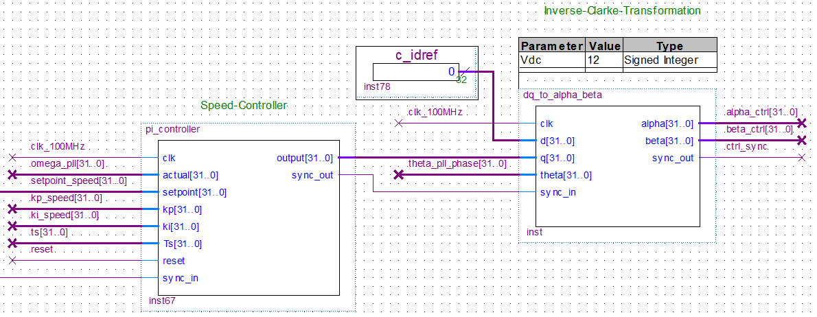
3. Speed-Controller
Now that I already had a PI-controller implemented, I took the same VHDL-block to create a speed-controller. The reference-value is a user-defined speed-setpoint, the actual value is the omega from my previous PI-controller of the PLL:
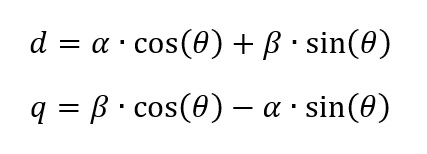
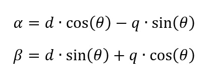
The only new thing is the inverse-park-transformation, but in general it is following the calculation of the park-transformation using the CORDIC-algorithm again:
So far, so good. But we still have a two-phase control-signal for a 6-phase motor. We are still missing a thing...
4. Generating PWM-signals for 6-phase BLDC
The six phases (a, b, c, d, e and f) can be controlled via a regular PWM. But the control-signals for these PWM-blocks have to be calculated using the alpha/beta-signals. For a three-phase motor we can use the well known inverse clark-transformation to calculate the signal a, b and c:

The signals will look like this:
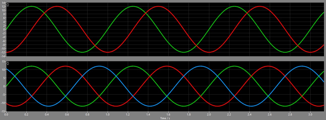
But for a 6-phase motor I had to find a new set of equations to calculate the signals for all six phases:
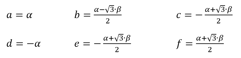
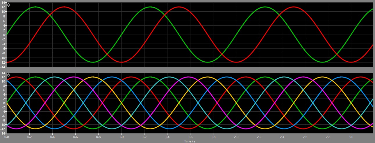
Now the signals will look like this:
Looking at the specifications of the BLDC-motor I realized, that it uses a special cross-pattern. So I had to change the signal-calculation once more:
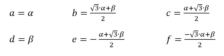
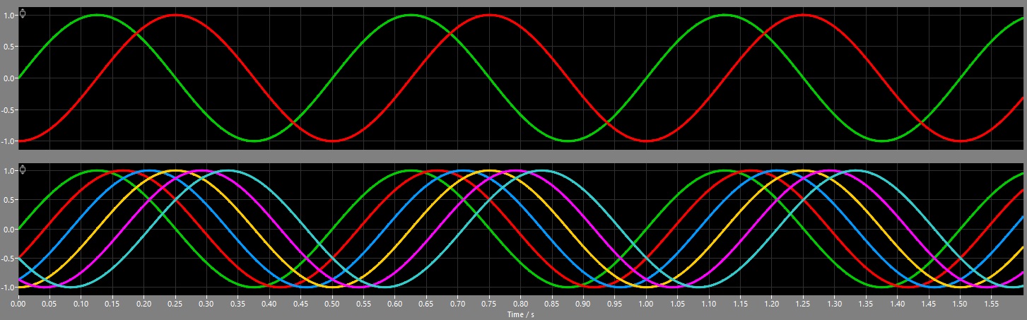
Resulting in the following signals:
The VHDL-code looks like this:
if (sync_in = '1' and state = 0) then
    -- preload multiplier with (sqrt(3)/2) * alpha
    mult_in_a <= to_signed(56755, 32); -- sqrt(3)/2 as Q15.16
    mult_in_b <= alpha;
    state <= 1;

elsif (state = 2) then
    -- copy result and preload multiplier with (sqrt(3)/2) * beta
    alpha_sqrt <= resize(shift_right(mult_out, 16), 32); -- sqrt(3)*0.5*alpha in Q15.16
    mult_in_a <= to_signed(56755, 32); -- sqrt(3)/2 as Q15.16
    mult_in_b <= beta;
    state <= state + 1;

elsif (state = 3) then
    -- copy result
    beta_sqrt <= resize(shift_right(mult_out, 16), 32); -- sqrt(3)*0.5*beta in Q15.16
    state <= state + 1;

elsif (state = 4) then
    -- calculation for 6-phase with 60° phase-shift
    --a <= alpha;
    --b <= shift_right(alpha, 1) + beta_sqrt; -- 0.5*alpha + 0.866025404*beta
    --c <= -shift_right(alpha, 1) + beta_sqrt; -- -0.5*alpha + 0.866025404*beta
    --d <= -alpha;
    --e <= -shift_right(alpha, 1) - beta_sqrt; -- -0.5*alpha - 0.866025404*beta
    --f <= shift_right(alpha, 1) - beta_sqrt; -- 0.5*alpha - 0.866025404*beta

    -- calculation for 6-phase with 30° phase-shift
    a <= alpha;
    b <= alpha_sqrt + shift_right(beta, 1);
    c <= shift_right(alpha, 1) + beta_sqrt;
    d <= beta;
    e <= -shift_right(alpha, 1) + beta_sqrt;
    f <= -alpha_sqrt + shift_right(beta, 1);
    sync_out <= '1';
    state <= state + 1;

elsif (state = 5) then
    -- back to idle-state
    sync_out <= '0';
    state <= 0;

end if;
After lot of conversions and calculations I finally had the desired control-signals for the six PWM-modulators.
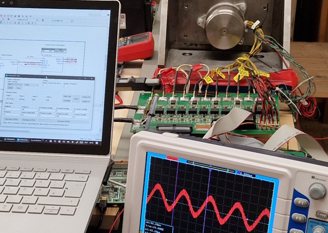
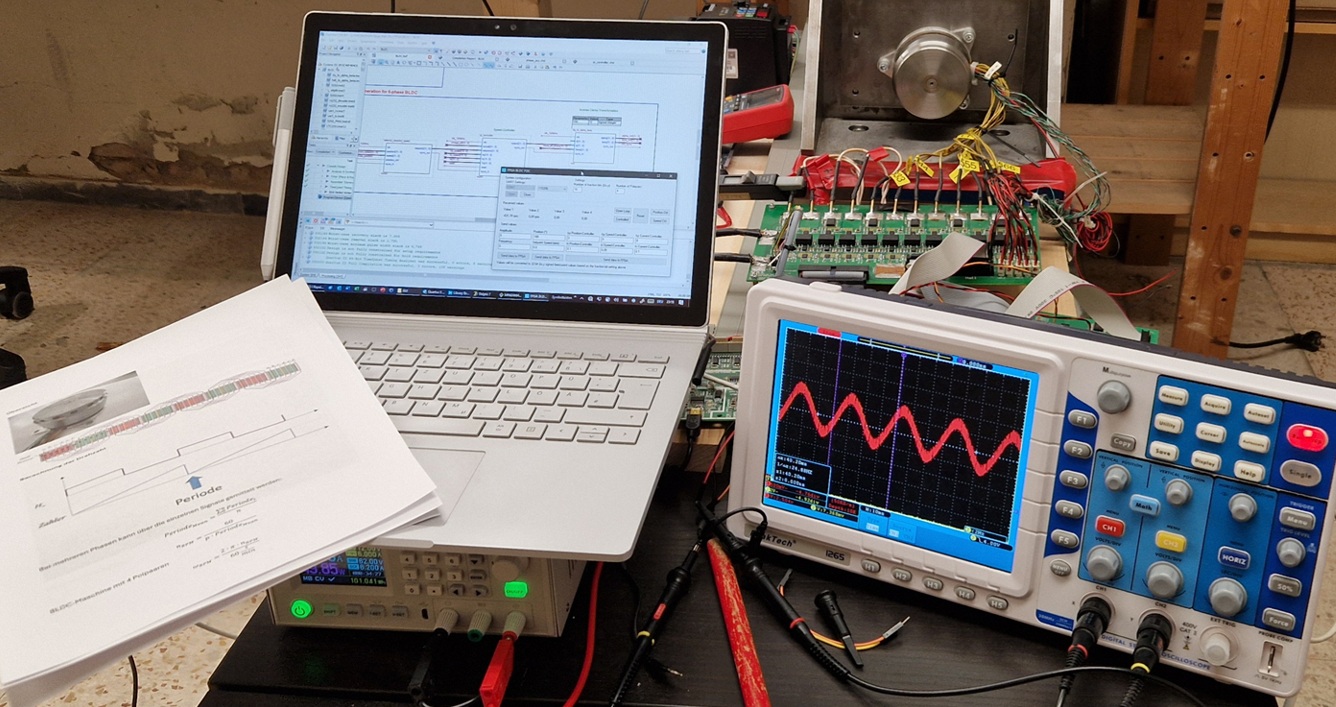
Test of the system
After testing the individual VHDL-blocks with some test-signals I finally could test the whole system. In 2014 I created an FPGA-test-board using an Altera Cyclone III FPGA (EP3C40F484C6). This board is connected to a power-board containing six low-voltage MOSFET H-bridges, connected to each phase of the motor:
In the end I implemented a full-featured FOC with position- and speed-controller able to define setpoints for acceleration, speed and position. Unfortunately I had some problems with the onboard current-sensors, so that I controlled the BLDC motor only using a speed-controller without controlling the current. But for a spare-time-project this was enough for now.
The whole code is available on Github in the repository FPGA_BLDC_FOC.
Comments